Top

The project checklist will determine the layout of the single and/or double brackets. Single & double brackets achieve an 80 – 280mm standoff as standard, bespoke sizes are possible on a short lead time. Stand offs greater than 300mm require additional cross bracing and we do not advise having a stand off of greater than 400mm in a facade or greater than 1000mm in a soffit application.
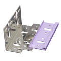
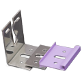
The FastFrame bracket is a three part component that must be used together. This unique design results in much greater fixing centres and therefor, will become more cost effective per metre square than a weaker bracket.
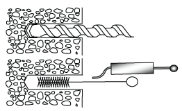
When fixing FastFrame brackets into concrete, a pull out test must be performed to verify the strength of the masonry. All drill holes should be thoroughly cleaned out and free from dust and grit before fixings are inserted.

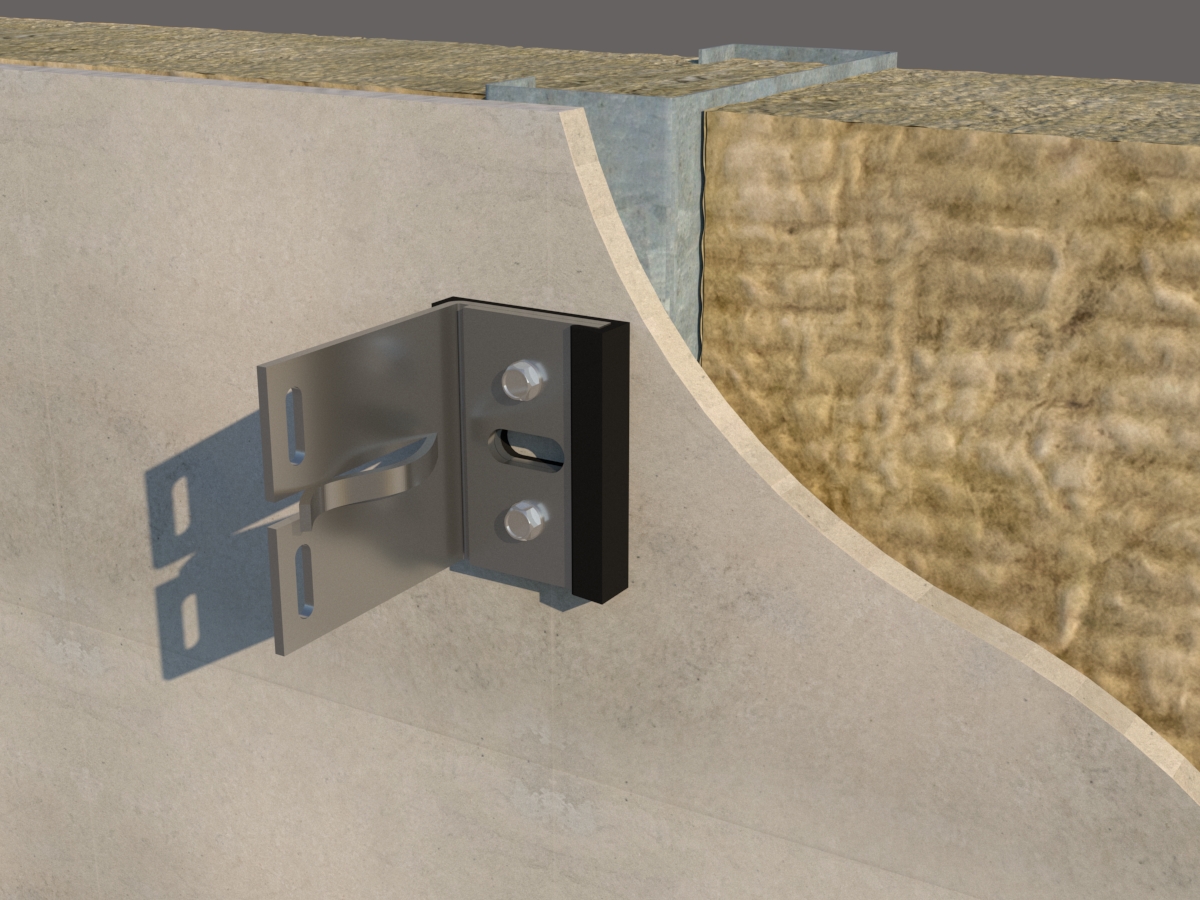
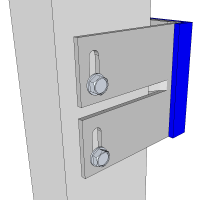
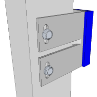
When fixing FastFrame brackets into concrete, ensure the fixings are placed in the larger elongated holes with the collar of the frame anchor plug on the face of the bracket.
When fixing FastFrame brackets onto steel or timber substrates, please ensure there are 2 anchors per single bracket or 4 anchors per double bracket and that they are placed in the smaller 6.5mm holes.
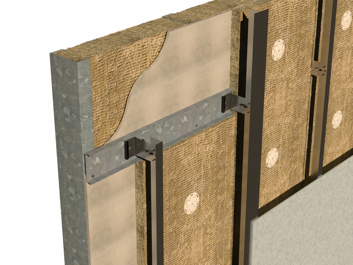
We can offer a simple and cost effective solution to solve the common issue of having a facade layout that doesn’t line up with the frame work underneath. By using horizontal steel top hat profiles to bridge between the frame, it means that the facade support system can be installed independently of the frame.
An individual rail will usually have only one fixed point bracket and the rest will be floating to allow for expansion. Consult your calculations return sheet for the locations of the fixed and floating point brackets on each rail length range.
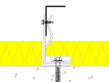
The PCF/44/4.8×19 bracket to rail fixings are positioned at the bottom of the hole to take the vertical deadload of the rail as well as the windload.
The PCF/44/4.8×19 bracket to rail fixings are positioned in the middle of the hole to allow the rails to expand and contract. These brackets only take wind load but minimal deadload
RAILS MUST ALWAYS BE INSTALLED VERTICALLY!
Although the rails would be fine being installed at an angle, the brackets are not designed to take any side load.
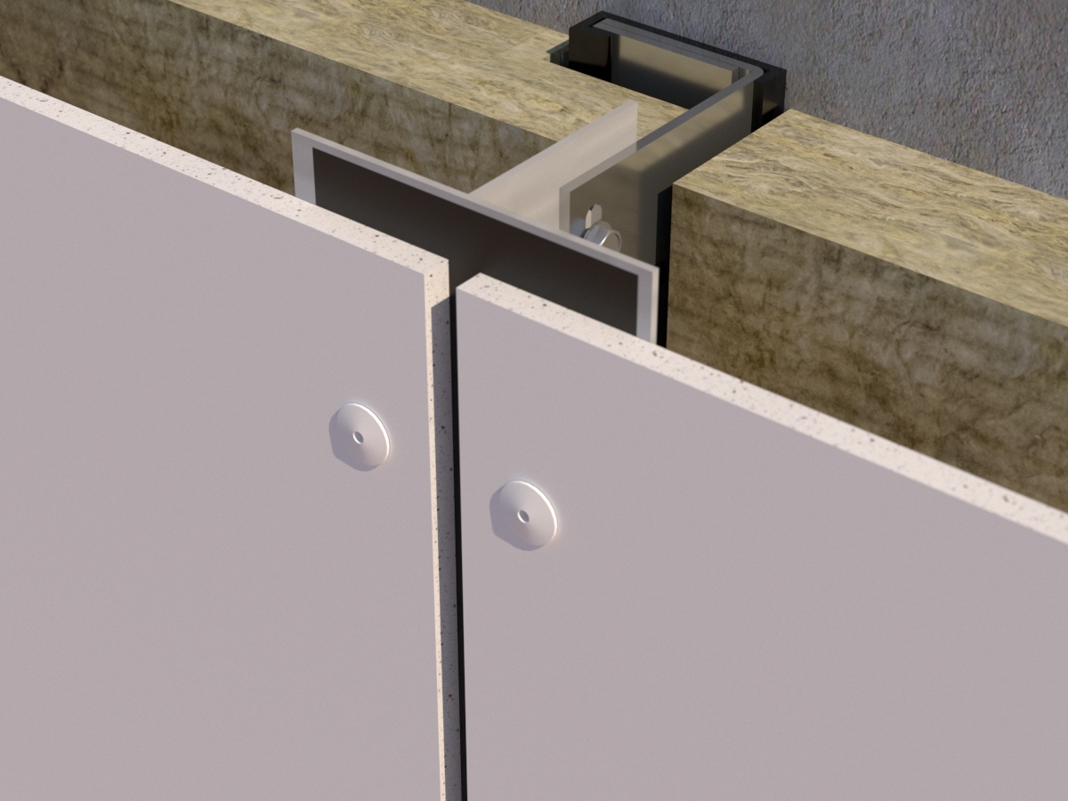
Where vertical joints occur within the cladding facade a Tee Rail should be inserted into the bracket clip.
Where intermediate panel support is required, insert an Angle Rail. Adjust where necessary.
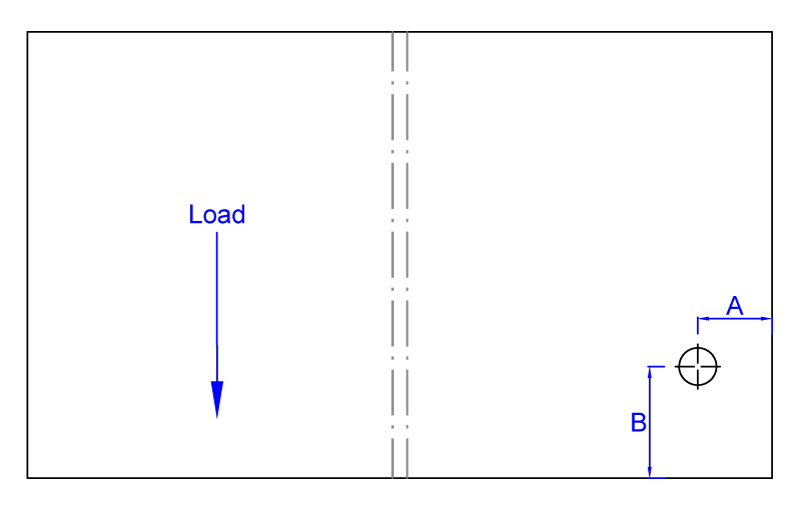
When fixing to the rail faces, always ensure that you have at least 2x the thickness of the fixing (or 10mm, whichever is greater) between the fixing centrepoint and the leg or edge of the rail (dim A). There must be at least 3x the thickness (or 15mm, whichever is greater) between the fixing and the bottom of the rail (dim B).

When you receive your bracket spacings back from us, they will dictate how much the rail can sail past the bracket. Rail cantilevers must not be more than 50% of the length of the span they are adjacent too. There MUST ALWAYS be a 10mm gap between rails going up the facade. Panels MUST NEVER span over rail joints. Support rails SHOULD NEVER span over the buildings movement joints unless specifically engineered to do so.
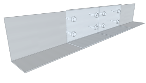
If you wish to join a rail to use off cuts then this is ok providing you do the following:
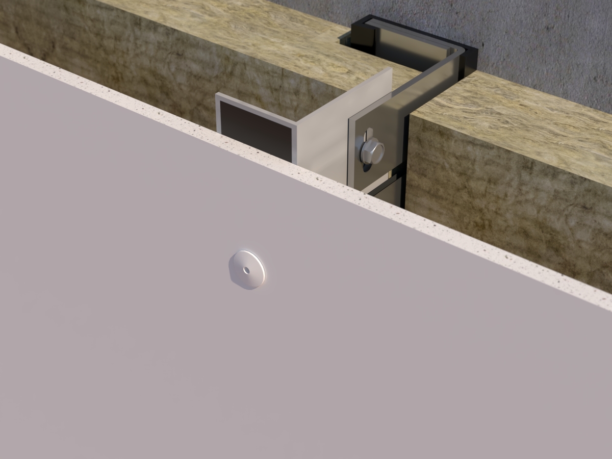
The insulation does not interfere with the rails or fixings
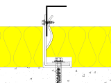
The insulation will have to be cut away to allow the leg of the rails to be fitted but will not affect the fixing of the rail to the bracket.
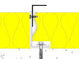
The insulation will have to be cut away to allow the leg of the rails to be fitted and the rail to bracket fixing is under the surface of the insulation making it very hard to fit.
Speak to one of the team today
Call us on +44 (0)1726 74771 or message us